Fixing Higher-than-Normal Voltage Readings
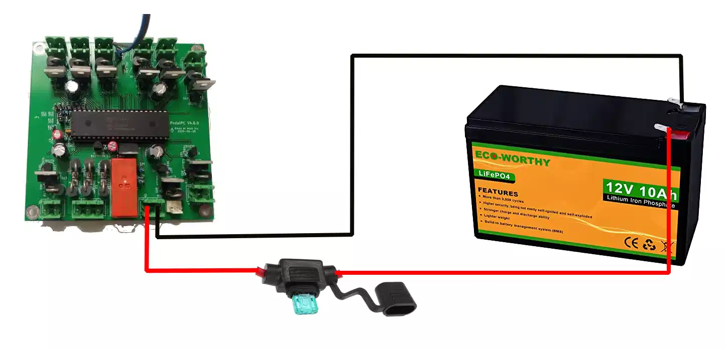
On the PedalPC, the power sockets and battery are all wired together in parallel, so all loads plus the battery are at nearly the same voltage. The circuit board on the PedalPC measures this voltage constantly, using it to calculate the power the generator produces and each device consumes. When the voltage gets above a certain threshold, it disconnects the generator from the power sockets and battery to prevent damaging them. It's therefore crucial that this voltage measurement be accurate.
I recently noticed the voltage on my machine creeping higher than normal at any given state of battery charge. (Voltage is proportional to a battery's state-of-charge—the greater its charge, the higher its voltage will be.) This made charging the battery more difficult, as I had to reduce my pedaling cadence to prevent the voltage from rising over the threshold cutoff. If I didn't, the generator would disconnect.
It also lengthemed the time required to charge the battery, because my reduced pedaling speed lowered the generator's power output.
Here's what was causing the voltage to creep upward, how I fixed it, and what I should have done differently.
What Caused it
To verify a problem existed, I measured the voltage at the battery terminals while pedaling using a digital voltmeter. The difference between the battery voltage and circuit board value was around 1 V. Clearly something was wrong.
Kirchoff's voltage law (KVL) states that sum of the voltages around any closed loop in a circuit is zero. If the voltage at the circuit board was higher than the voltage at the battery, then a voltage drop must exist somewhere inbetween the board and the battery.

From Ohm's law, the voltage drop in each of the wires is the current flowing through the wire (i.e., the battery current) times the wire's resistance:
V = I x R

where:
V = voltage drop
I = current
R = resistance
Normally, the resistance of the two wires should be very close to zero, so the voltage drop in the wires should also be close to zero. A poor connection anywhere between the battery and the circuit board, however, would introduce a small amount of resistance at that point in the circuit. Since the this is a high-current circuit, this small resistance will cause a non-neglegible voltage drop.
So, I figured a poor connection somewhere between the circuit board and the battery was causing the problem.
What I Did
Rather than attempt to isolate the problem further, I decided instead to simply tighten all the connections. I set the battery off timeout on the PedalPC to 90 seconds and stop pedaling to allow the PedalPC's computer to safely shutdown and power off. I pulled the battery connector from the circuit board and removed the wires from the connector. I cleaned, trimmed, and straigthened the ends of the wire, re-inserted them into the connector, and tigthened them down tightly.
I then pulled the female spade terminals off the battery terminals, crimped them a little with pliers so they would grip onto the battery terminals a little more tightly, and slid them back over the battery terminal spade, which reconnected the battery to the circuit board.
Normally reconnecting the battery will cause the LEDs on the PedalPC to blink as the circuit board goes through its calibration process. But this wasn't happening. The circuit board behaved as if the battery was still disconnected.
I removed the fuse holder and discovered it had blown. Why? I foolishly hadn't disconnected the battery before removing the wires from the circuit board connector. The free ends of the wires likely shorted together while I was working on them.
As soon as I replaced the fuse, the LEDs began blinking as expected. I started pedaling, and the voltage readings were back to normal.
What I Should Have Done
Since I had a voltmeter, I should have measured the voltage drop across each battery wire separately first, from its battery terminal to its circuit board connector, while the battery was powering a load. These measurements would have told me which wire was at fault. I could have then done further testing on that wire to isolate the faulty connection.
Once I isolated the fault, I should have first disconnected the wire from the battery terminals, then fixed the faulty connection. That would have prevented blowing the fuse.
If I hadn't had a voltmeter, I should have simply tried replacing the fuse first. I had this problem a few years ago and fixed it by replacing the fuse. It's quite possible the fuse was the cause this time, too.
If replacing the fuse didn't fix the problem, I then should have switched the procedure I followed. I should have removed the connectors from the battery terminals first, crimped them , then—while the battery was still disconnected--safely remove the wires from the connector to trim and clean them. After re-inserting the wires into the connector and re-connecting it to the board, I could reattach the battery connectors back on the battery terminals.
Lessons Learned
- Isolate an electrical problem as much as possible before attempting to fix it.
- Always de-energize a circuit before working on it!