How the PedalPC Works
My pedal-powered computer desk, which I call the PedalPC, is composed of six parts:
- desk frame
- generator
- battery
- control board
- power sockets
- single-board computer

Each part is described below, followed by a brief description of the software that controls the desk.
Desk Frame
The desk frame is made mostly of 1" x 2" / 25mm x 50mm anodized aluminum rectangular tubing. I chose this material because it is rugged, lightweight, rustproof, and doesn't need painting. (I also selected it because it is a key component in the bicycle trailers my wife and I manufacture, so we have a lot on hand.)
I tried several different seating positions, from fully upright (like sitting on a bicycle) to fully recumbent. I found a semi-recumbent, chair-like seating position to be the most comfortable for typing and pedaling at the same time. To prevent the user's knees from striking the underside of the desk in this position, I use shorter-than-normal bicycle cranks (125 mm vs 170-175 mm).
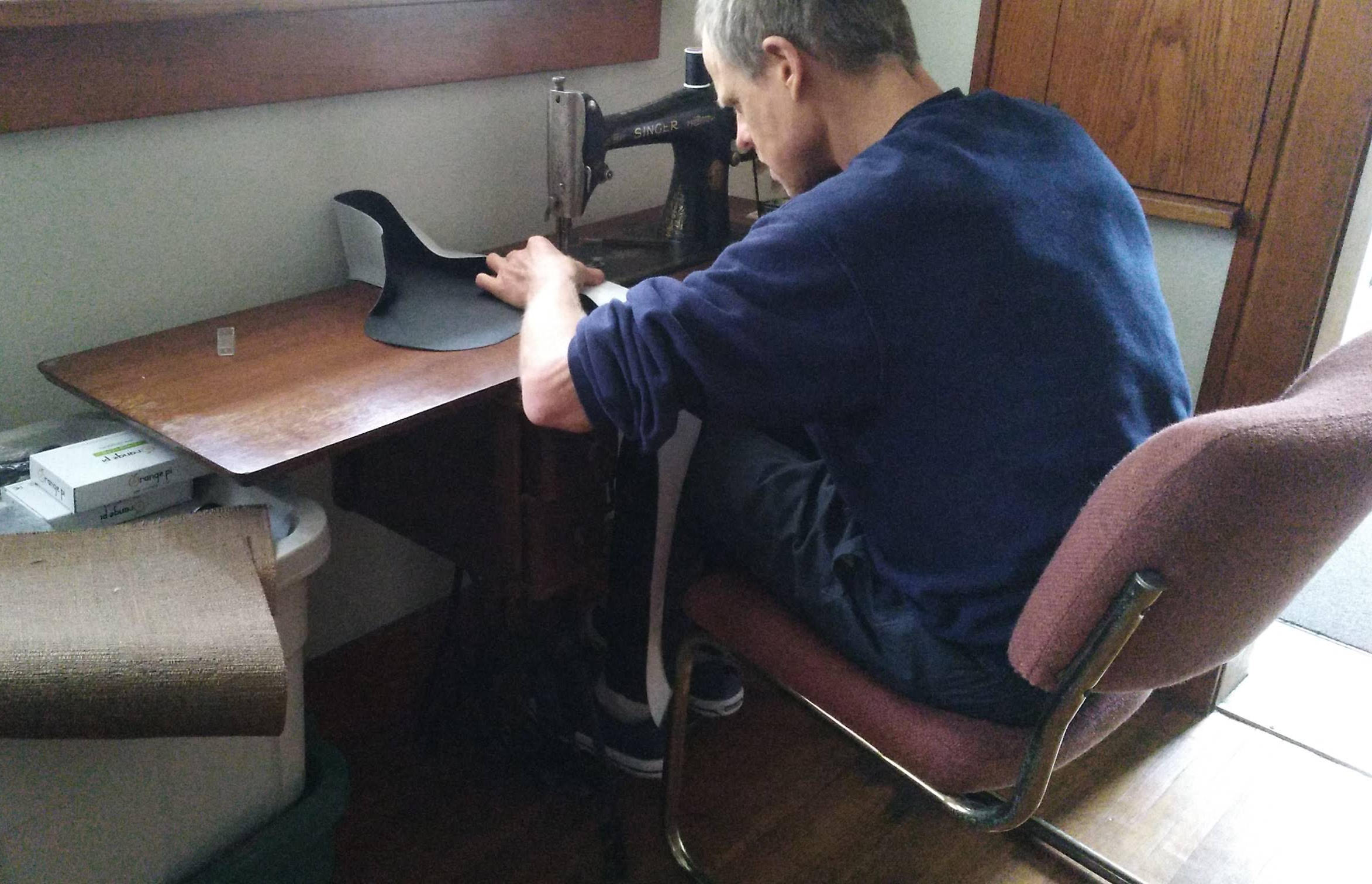
Sitting for long periods while pedalling can be uncomfortable, especially when your hands can't be used to help bear your weight like on a traditional bicycle. I tried more than half a dozen commercially-available bicycle saddles, but never found one comfortable for this application. I ended up making my own, patterned roughly on a recumbent exercise bike I found comfortable. I sew each seat using (what else?) a treadle-powered sewing machine.
The frame folds up to make it easy to move from one location to another. Wheels on its rear legs allow it to be rolled on the floor when in the folded position. The machine weights about 54 lbs, and can be carried by one person if necessary.
Generator
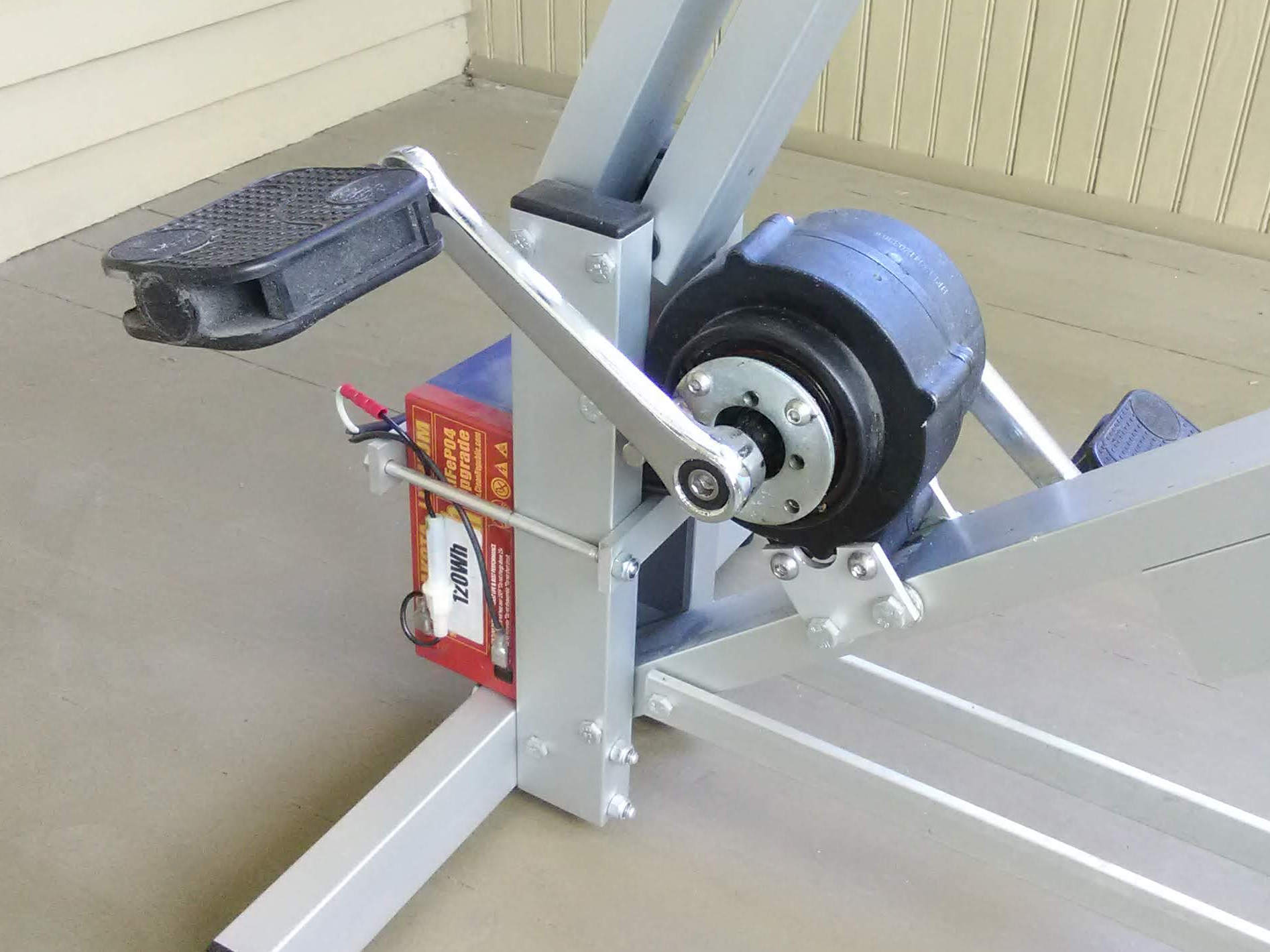
The generator I'm currently using is a 36V 250W modified Bofeili mid-drive electric bike motor direct-drive electric bicycle rear hub motor. Six Schottky power diodes mounted on the control board rectify its unregulated, three-phase AC output to DC.
Any permanent-magnet motor will generate electricity when it is driven; the challenge is getting it to spin fast enough to generate usable electricity. Most people pedal at a relatively slow cadence (40-80 RPM) when using a bike desk. Most motors, however, need to spin much faster (usually > 3000 RPM) to generate significant amounts of electricity at a useful voltage.
Electric bicycle motors are designed to rotate at a speed much closer to a bicyclist's cadence. They are rugged, efficient (usually ~80%), relatively compact, and brushless (which reduce noise and maintenance). For this reason, I have mostly used electric bike motors for the self-powered desks I've built.
There are two types of electric bike motors, hub motors and mid-drive motors. Hub motors are built into the front or rear wheel hub of a bike. Mid-drive motors are built into the bicycle's crankset, in the middle of the bike (hence the name). Both work well as human-powered generators.
Hub motors usually cost 1/3 to 1/2 the price of a mid-drive motor, but when the cost of the extra hardware required by a hub motor (bottom bracket spindle, cranks, chain, and sprockets) is included, the cost difference isn't as significant. A hub motor generator requires more space, since the motor and cranks are separate units. Care is also required to prevent dangling cables from getting caught between the chain and sprockets. (I speak from experience!)
Hub motors, however, are more readily available. You can change the power output at a given cadence by changing the size of the sprockets.
A mid-drive motor requires some modifications to be used as a generator, since due to the way it is built, its cranks won't drive the motor.
A mid-drive bike motor has basically five parts: the crankset, motor, two freewheels, and drive hub holding the chainwheel. (When used as a generator, the chainwheel is removed since it isn't driving a chain.)
As you may know, a freewheel is a mechanical device that transfers rotary motion in one direction only, either clockwise or counterclockwise, depending on the direction it is mounted. One of the bike motor's freewheels connects the cranks to the drive hub. The other freewheel connects the motor to the drive hub.
Here's how the parts work together on an electric bike. When the bike's motor is on, the motor freewheel is engaged and drives the drive hub, while the crank freewheel disengages the crank. This allows the motor to propel the bike without the cyclist needing to pedal at the same speed as the motor is turning.
When the bike's motor is off, the crank freewheel engages the cranks with the drive hub, while the motor freewheel disengages the motor. This allows the cyclist to propel the bike without the added drag of the motor.
Notice if the motor's freewheel was engaged while the cyclist was pedaling, then the cranks would drive the motor via the drive hub, allowing it to function as a generator.
There are two ways to achieve this. I have tried both. Both methods work.
The first and easiest method is to mount the mid-drive motor assembly backward on the frame, so the right side is now on the left. This reverses the direction of engagement for both freewheel relative to the direction of crank rotation. Now, the drive hub will drive the motor when the hub is rotated in the same direction as the cranks. However, since the crank freewheel has been rotated, too, the cranks will no longer drive the drive hub! A simple fix for this problem is to mount a pin externally on the drive hub. When the cranks are pedalled in the forward direction, the left crank will strike the pin and rotate the drive hub.
The second method is to disassemble the motor assembly and weld the sprocket on the motor freewheel's hub to prevent it from freewheeling. This method is necessary when there is no easy way to mount a pin on the drive hub.
Battery
A buffer is required between a pedal-powered generator and its load. That's because a pedal-powered generator's power fluctuates with each pedal stroke, and also because the power demands of the equipment it supplies fluctuates, too.
The PedalPC uses a 12V lithium-ion phosphate (LiFePO4) battery wired in parallel to the generator for its buffer. I chose a LiFePO4 battery because it is safer and more rugged than a lithium-ion battery, and smaller and lighter than a comparable lead-acid battery. It also has a long lifetime, maintaining up to 80% of its capacity over 2000 discharge cycles. (At the time of this writing, the battery on the machine I am currently using is over 4 years old.)
The battery has a rated capacity of 120 Whr. This means it can store enough energy to power a 12 W laptop for about 120 Whr / 12 W = 10 hours, or a small 5W modem + web server load for 120 Whr / 5W = 24 hours. These are theoretical values; actual values are probably somewhat less.
The length of time required to recharge it depends on how much surplus power you are producing. I usually produce about 30-40 W of surplus power while I'm working on my computer, so it takes me about 120 Whr/ 30 W = 4 hours to fully recharge a dead battery.
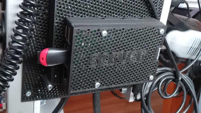
Control Board
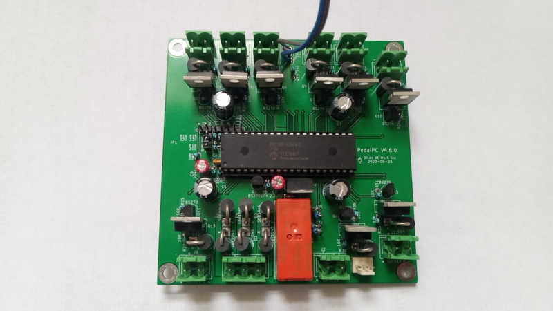
The control board manages the power flowing from the generator through the battery, power sockets, and cooling fan.
The generator is connected to the board through a relay, a type of electrical switch. When the battery voltage nears its upper limit, the relay opens and disconnects the generator. This prevent damage to the battery and any loads connected to the PedalPC.
The power sockets and cooling fan are connected to the board through power MOSFETs, another type of electrical switch that uses less power than a relay. If any device plugged into a power socket draws too much current, its power MOSFET turns off to prevent damage. If the battery voltage drops too low, all the power MOSFETs are turned off to prevent draining the battery.
A bi-color LED built into the front of the desktop provides a simple indicator of the board's status. When you are charging the battery, the LED is green. If you pedal too slowly to charge the battery, it turns orange. If this continues for more than a few seconds, it starts blinking red to alert you to pedal faster. If you pedal too fast, it rapidly blinks an alternating green and red pattern.
If you stop pedalling entirely, it slowly blinks once every 10 seconds to remind you the battery is draining. In this state, the battery's state-of-charge determines the blink color.
Device current is calculated by measuring the voltage drop across ten current sense resistors (one for the battery, one for the cooling fan, and one for each of the eight power sockets). Since current is conserved, the generator's current output is the net sum of all the measured currents.
The board is controlled by a Microchip PIC 18F45K42 microcontroller. Twenty of the 18F45K42's analog-to-digital (ADC) converters measure current and voltage, which are multiplied to together to calculate power consumption and generation.
I solder each board by hand using a portable 12 V soldering iron. The soldering iron is powered by the PedalPC's battery.
Power Sockets
The PedalPC's power output is fed out through four pairs of 5V DC USB power sockets and four 12V DC automotive power sockets.
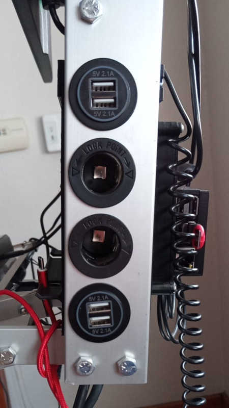
There is an additional header on the control board for supplying power to a personal cooling fan.
The PedalPC has no built-in AC power sockets. To power a laptop or other piece of equipment, an adapter is usually required. The adapter is plugged into the socket, then the device plugged into the adapter.
The reason I designed it this way is because a human being can only produce a limited amount of power, and each time power is converted from DC-to-AC or AC-to-DC, some of that power is wasted.
Most equipment capable of being powered by the PedalPC (laptops, phones, modems, printers, etc) actually use DC, not AC. The DC is supplied by an AC-to-DC adapter (aka "wall wart"). To get the most power out of the PedalPC, it is best to bypass these adapters and power the equipment directly from DC.
Many modems, monitors, and battery chargers requiring 12V DC input can be from the PedalPC's power socket. No adapter is necessary, just a 12V DC power cord. Equipment that operates at other DC voltages will require a DC-to-DC adapter, usually sold as "car adapters". Laptops, for instance, usually operate at more than 12V DC and will need a laptop adapter. USB-powered devices likes phones and tables operate on 5V DC and can be powered from the USB sockets. Other equipment that require 110V AC because they lack an external power adapter can be powered using a 12V DC-to-110V AC inverter.
Single-Board Computer
A low-power single-board computer (SBC) connected to the microcontroller's serial port generates a dashboard you can view using a web browser. The dashboard is accessible from any computer or phone on your local network. If no network is available, it creates a wifi access point to which you can connect instead.
I have used several different SBCs over the past 10 years. I currently use a Raspberry Pi 3B. Other boards I have used include an Orange Pi PC+, Orange Pi Plus 2E, and an Orange Pi Zero LTS.
The dashboard displays the current power output of the generator and each device connected to the desk, current session statistics (elapsed time, total energy generated, and approximate calories burned), battery status, and the average power output and total energy produced for each of the past 7 days. It also plots a minute-by-minute graph of each device's power consumption, to easily see how much energy each device uses and how it changes over time.
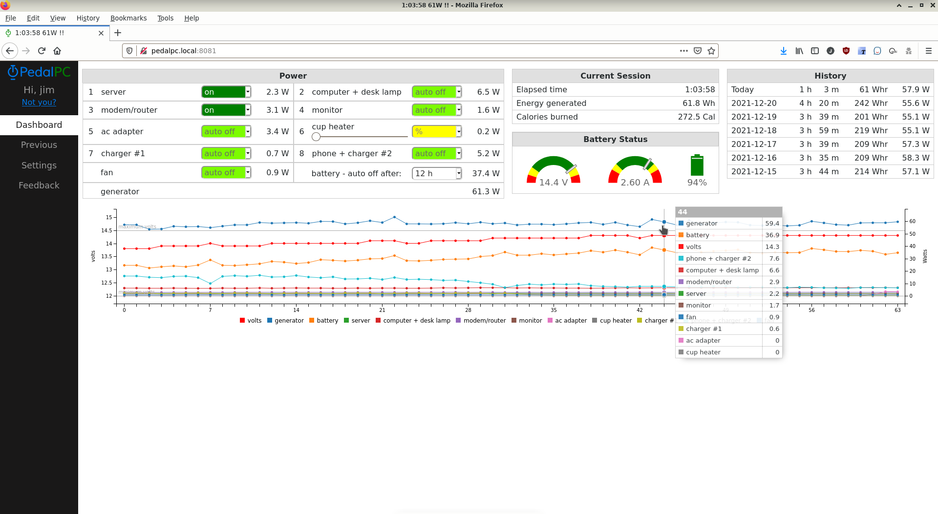
You can also turn devices on and off via the dashboard and control how long they will remain powered if you stop pedaling.
Reading and displaying this data imposes minimal overhead on the SBC. This allows the SBC to be used simultaneously for other tasks if desired, making them human-powered as well. These could include a web kiosk, NAS device, VPN gateway, Nextcloud host, or a self-hosted web server. (The web site you are viewing now actually came from a web server running on my SBC through a CDN.
Software Stack
The server and microcontroller communication software are written in Python 3 using the aiohttp, asyncio, and serial_asyncio Python libraries. The dashboard front end uses vanilla javascript and the C3.js charting library. Data is stored in a SQLite database.
The firmware on the 18F45K42 is written in Great Cow BASIC, an open-source implementation of BASIC for Microchip PIC and AVR microcontrollers. The program was compiled each time directly on the SBC from the command line and flashed to the microcontroller over the SBC's GPIO pins using Darron Broad's excellent Pickle ICSP software.