How to Program a PIC Microcontroller Using a Raspberry Pi or Orange Pi
I have used PIC microcontrollers on many projects, including the PedalPC. I like using them because:
- they have a wide variety of useful peripherals, like 12-bit differential ADCs and on-board Full Speed USB 2.0,
- they're inexpensive (about 1/3 to 1/2 the cost of comparable AVR microcontrollers when you're purchasing them in low quantities like I do), and
- almost all chips with 40 pins or less are available in an easy-to-solder DIP form factor.
Compiling programs for PIC microcontrollers is easy on a low-resource single board computer like a Raspberry Pi using open-source program languages like Great Cow Basic or JAL. (I may describe how to do this in another post).
The challenge is how to get the compiled programs onto the chip. The usual technique is to use a dedicated external device (called a programmer) that attaches both to your computer and to the chip and transfers the compiled program into the memory of the microcontroller.
These programmers can be somewhat expensive (usually at least $30) and are another piece of specialized hardware you have to keep around.
However, with the right software and a few resistors, you can transfer your programs directly to your PIC using the GPIO pins of a single-board computer (SBC) like a Raspberry Pi or Orange Pi. This can be very useful if you are already using a SBC to read data from the PIC, like I do on the PedalPC.
In this tutorial, I will explain how to:
- install the software needed to program the PIC,
- connect the PIC to the GPIO pins on your single-board computer,
- create the configuration file required by the program,
- install a driver if your computer is unsupported,
- upload the file to your PIC, and
- troubleshoot it if it didn't work out properly.
The in-circuit serial programming (ICSP) software we'll be using in this tutorial is an excellent utility called Pickle written by Darron Broad. It works with many single-board computers running Linux, and requires only a few resistors to successfully program most PICS at 3.3V. (Programming a 5V PIC in-circuit will require an inexpensive 4-channel 5V-to-3.3V logic level converter, which are widely available on eBay and other sites.)
This method works only with PIC microcontrollers that can be programmed using the low-voltage programming (LVP) method, which includes most common PICs in use today. (Darron has a list of supported PIC microcontrollers on his site as well as a large table of PICs that have been tested.) It will not work with older chips that require the high-voltage programming (HVP) method. For those chips, you'll need a programmer, not just a few resistors or level converter.
Installing the Software
Use the following commands to install the Pickle ICSP program onto your SBC:
cd /tmp
wget http://wiki.kewl.org/downloads/pickle-4.20.tgz
tar zxf pickle-4.20.tgz
cd pickle-4.20/
make
sudo make install
This compiles and installs the Pickle utilities in /usr/local/bin on your SBC.
Choose Your Programming Pins
You'll need 3 (or 4) GPIO pins to connect to VPP, PGC, and PGD (and PGM, if your PIC requires it--most chips nowadays don't.) These pins can't currently be in use by your kernel. You can see the GPIO pins being used by:
ls /sys/class/gpio | grep gpio[0-9_]
If no pins are listed, then you can choose any of the available GPIO pins on your board. If you need to use a pin already in use, you can make it available this way:
sudo echo <pin number> | /sys/class/gpio/unexport
Here's a list of the Raspberry Pi's GPIO pins:
| Raspberry Pi 2 and 3 GPIO pins | |||
|---|---|---|---|
| header pin | function | header pin | function |
| 01 | 3V3 | 02 | 5V |
| 03 | GPIO0/GPIO2 | 04 | 5V |
| 05 | GPIO1/GPIO3 | 06 | GND |
| 07 | GPIO4 | 08 | GPIO14/TX |
| 09 | GND | 10 | GPIO15/RX |
| 11 | GPIO17 | 12 | GPIO18 |
| 13 | GPIO21/GPIO27 | 14 | GND |
| 15 | GPIO22 | 16 | GPIO23 |
| 17 | 3V3 | 18 | GPIO24 |
| 19 | GPIO10 | 20 | GND |
| 21 | GPIO9 | 22 | GPIO25 |
| 23 | GPIO11 | 24 | GPIO8 |
| 25 | GND | 26 | GPIO7 |
| ID_SD | EEPROM | 27 | 28 |
| 29 | GPIO5 | 30 | GND |
| 31 | GPIO6 | 32 | GPIO12 |
| 33 | GPIO13 | 34 | GND |
| 35 | GPIO19 | 36 | GPIO16 |
| 37 | GPIO26 | 38 | GPIO20 |
| 39 | GND | 40 | GPIO21 |
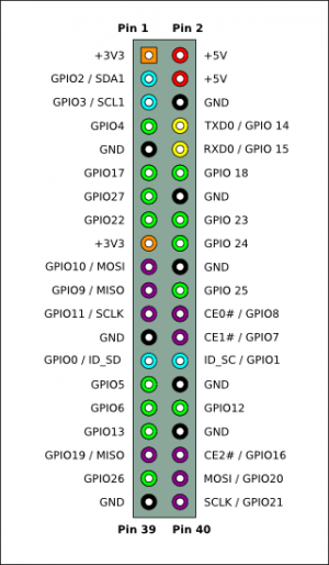
For the Raspberry Pi 2 or 3, I recommend using GPIO_9, GPIO_10, and GPIO_11. For PICs like the 16F1788, where the PGD and PDC pins are also serial port pins Rx and Tx (respectively), pins GPIO_14, GPIO_15, and GPIO_18 work even better, because you can use same pins to both program the PIC AND communicate with it over the PIC's serial port.
This assumes your PIC doesn't have or need to use a PGM pin to program it in LVP mode. If the PIC you are using does (e.g., the 18F14K50), you'll need to select a fourth GPIO pin for that function as well.
Here's a list of the pins on the Orange Pi+ 2:
| Orange Pi Plus 2 40-pin header | |||||
|---|---|---|---|---|---|
| pin | function | sysfs GPIO number | pin | function | sysfs GPIO number |
| 1 | 3.3V | 2 | VCC-5V | ||
| 3 | PA12 (TWI0-SDA/DI_RX/EINT12) | NA | 4 | VCC-5V | |
| 5 | PA11 (TWI0-SCK/DI_TX/EINT11) | NA | 6 | GND | |
| 7 | PA6 (SIM_PWREN/PWM1/PA_EINT6) | gpio_6 | 8 | PA13 (SPI1_CS/UART3_TX/PA_EINT13) | gpio_13 |
| 9 | GND | 10 | PA14 (SPI1_CLK/UART3_RX/PA_EINT14) | gpio_14 | |
| 11 | PA1 (UART2_RX/JTAG_CK0/PA_EINT1) | gpio_1 | 12 | PD14(RGMII_NULL/MII_TXERR/RMII_NULL) | gpio_110 |
| 13 | PA0 (UART2_TX/JTAG_MS0/PA_EINT0) | gpio_0 | 14 | GND | |
| 15 | PA3 (UART2_CTS/JTAG_DI0/PA_EINT3) | gpio_3 | 16 | PC4 (NAND_CE0) | gpio_68 |
| 17 | 3.3V | 18 | PC7 (NAND_RB1) | gpio_71 | |
| 19 | PC0 (NAND_WE/SPI0_MOSI) | NA | 20 | GND | |
| 21 | PC1 (NAND_ALE/SPI0_MISO) | NA | 22 | PA2 (UART2_RTS/JTAG_DO0/PA_EINT2) | gpio_2 |
| 23 | PC2 (NAND_CLE/SPI0_CLK) | NA | 24 | PC3 (NAND_CE1/SPI0_CS) | NA |
| 25 | GND | 26 | PA21 (PCM0_DIN/SIM_VPPPP/PA_EINT21) | gpio_21 | |
| 27 | PA19 (PCM0_CLK/TWI1_SDA/PA_EINT19) | NA | 28 | PA18 (PCM0_SYNC/TWI1_SCK/PA_EINT18) | NA |
| 29 | PA7 (SIM_CLK/PA_EINT7) | gpio_7 | 30 | GND | |
| 31 | PA8 (SIM_DATA/PA_EINT8) | gpio_8 | 32 | PG8 (UART1_RTS/PG_EINT8) | gpio_200 |
| 33 | PA9 (SIM_RST/PA_EINT9) | gpio_9 | 34 | GND | |
| 35 | PA10 (SIM_DET/PA_EINT10) | gpio_10 | 36 | PG9 (UART1_CTS/PG_EINT9) | gpio_201 |
| 37 | PA20 (PCM0_DOUT/SIM_VPPEN/PA_EINT20) | NA | 38 | PG6 (UART1_TX/PG_EINT6) | gpio_198 |
| 39 | GND | 40 | PG7 (UART1_RX/PG_EINT7) | gpio_199 | |
For this board, I recommend using either gpio_1, gpio_0, and gpio_3; or gpio_13, gpio_14, and gpio_110. The latter option is best if you want to communicate with the PIC's serial port and the PIC's serial port pins are also programming pins.
Again, this assumes your PIC doesn't need to use a PGM pin to program it. If it does, you'll need an additional GPIO pin for that function, too.
A sidenote: It took me a while to figure out how the pins are numbered on the Orange Pi boards.
The GPIO pins are identifed by a letter corresponding to a bank location and a two-digit number associated with its position in that bank. For instance, pin "PD14", which is in the 12th position on the header, is the 14th pin in bank "D".
This letter-and-number system must be converted to a pure number that Linux's sysfs understands. The formula to do this is:
GPIO number = (position of letter in alphabet - 1) x 32 + pin numberFor this pin, since "D" is the fourth letter of the alphabet:
<p><code>GPIO number = (4 - 1) x 32 + 14 = 110</code></p>
Therefore, header pin #12 is gpio_110.
I used this formula to calculate the pin numbers listed in the table.)
The table is taken from the Orange Pi Plus 2 linux-sunxi wiki). Other Orange Pi boards may have diffferent configurations. You can look up other Orange Pi boards from the Xunlong section of the linux-sunxi wiki. (Xunlong is the manufacturer of Orange Pi boards.)
Some of the I/O pins on the header may be configured for other tasks and aren't available to use as general-purpose I/O pins. How to determine which pins are available depends on which Linux kernel your board uses. There are two basic types, older 'legacy' (3.x) kernels and newer 'vanilla' (4.x) kernels. You can determine which Linux kernel you are using via.
$ sudo uname -a
[sudo] password for user:
Linux orangepiplus 3.4.112-sun8i #14 SMP PREEMPT Tue Jul 5 16:28:14 CEST 2016 armv7l GNU/Linux
The version number is listed after the words 'Linux' and your hostname. In this case, it's 3.4.112. If it's less than 4, you are using a 'Legacy' kernel. If it's > 4, then you're using a 'vanilla' kernel.
Legacy kernels are configured using a 'fex' file. This fex file is compiled into a binary and read at boot. To see how the pins are configured, you have to decompile this binary and read the configuration gpio configurations. The command to do this is:
sudo bin2fex /boot/script.bin | grep gpio_
Newer kernels have a different configuration system known as a 'device tree'. Follow these instructions to view your settings.
Creating the Configuration File
Once you know which GPIO pins you can use to program your PIC, you create the configuration file required by Pickle for programming the chip. This file is named '.pickle' and stored in your home directory.
A sample file is created when you install the software. You can either edit the existing file or create a new one.
You can run this command to create the file you need for a Raspberry Pi 2 or Raspberry Pi 3:
cat > .pickle <<EOF
DEVICE=RPI2
SLEEP=1
BITRULES=0x4F00
VPP=9
# set PGM = -1 if not used, otherwise use the correct pin number below
PGM=-1
PGC=10
PGD=11
EOF
In this configuration, GPIO pins 9, 10, and 11 of the Raspberry Pi will be connected to the VPP, PGC, and PGD pins on the microcontroller. PGM won't be used. If your chip requires a PGM pin to program it using LVP mode, you'll need to change the "-1" to the GPIO pin number you'll be using for that function.
Here's the command to run to create the configuration file for an Orange Pi+ 2:
cat > .pickle <<EOF
# Linux bit-banging GPIO
#DEVICE=/dev/gpio-bb
# original Orange Pi, Orange Pi PC, Orange Pi PC Plus, or Mini
#DEVICE=OPI
# Orange Pi Zero
#DEVICE=OPI0
# Orange Pi Plus or Orange Pi Plus 2
DEVICE=OPIP
SLEEP=1
# I/O bit rules.
# These rules determine the polarity of the control lines and whether
# data input requires data output pulled high.
# 0x0001 PGD_OUT_FLIP
# 0x0002 PGC_OUT_FLIP
# 0x0004 VPP_OUT_FLIP
# 0x0008 PGD_IN_FLIP
# 0x0010 PGD_IN_PULLUP
# 0x0020 PGM_OUT_FLIP
# 0x0040 VPP_OUT_CLOCK
# These rules are for GPIOs on program exit.
# 0x0100 PGD_RELEASE
# 0x0200 PGC_RELEASE
# 0x0400 PGM_RELEASE
# 0x0800 VPP_RELEASE
# 0x1000 VPP_RUN
# This rule enables shift with irq lock for GPIO BIT-BANG.
# 0x2000 BB_LOCK
# This rule re-enables the ALT0 function when an R-PI GPIO is released.
# 0x4000 ALT_RELEASE
# We want VPP in 'run' mode and PGC & PGD released for use by UART3
BITRULES=0x4F00
BUSY=0
#PGD - pin #8 (PA13/UART3_TX -> sysfs 13)
# Note: PGD can also be UART_RX on many PICs
PGD=13
#PGC - pin #10 (PA14/UART3_RX -> sysfs 14)
# Note: PGC can also be UART_TX on many PICs
PGC=14
#VPP - pin #12 (PD14 -> sysfs 110)
VPP=110
#PGM - not used
PGM=-1
DEBUG=10
EOF
Here, we're using gpio_13 for PGD, gpio_14 for PGC, and gpio_110 for VPP. I chose these particular pins because some PICs (like the 16f1788 I'm currently using) have an alternate mapping of their serial Tx and Rx pins over the PGC and PGD pins, respectively. This allows me to use the same lines to both program the chip and communicate with the chip over it's UART. This frees up two extra pins on both the board and the chip.
This is how it looks when wired to my Orange Pi Plus 2E board:
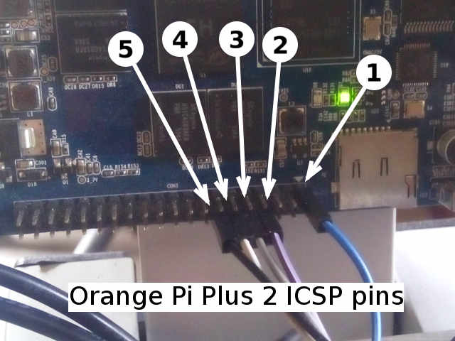
The leads in the photo above above are wired as follows:
- VDD
- PGD
- PGC
- VPP
- GND
This arrangement will also work on an Orange Pi PC or Orange Pi PC Plus.
Install Bit-Bang Driver (for other single-board computers)
Pickle supports all Raspberry Pi boards, and support was added for most Orange Pi boards since version 4.0f. If your board is not supported (Odroid C2, Tinkerboard, etc.), you will need to install Darron Broad's Linux bit-bang driver. First, install Mercurial if it isn't installed on your Pi already:
sudo apt-get install mercurial
Next, clone his repository and run the install script:
hg clone http://hg.kewl.org/pub/gpio-bb
cd gpio-bb
make
sudo make install
It should now show up in your list of installed modules:
lsmod | grep gpio_bb
As installed, you'll need to be root to use the bit-bang driver (and therefore program your chip). To change that, create a group for users of the driver and add yourself to the group:
sudo addgroup gpiobb
sudo chgrp gpiobb /dev/gpio-bb
sudo adduser your_username gpiobb
Update the modprobe configuration file so it will load each time you reboot your machine by adding this to /etc/modprobe.d/modprobe.conf (you may need to create the file if it doesn't exist):
install gpio-bb modprobe --ignore-install gpio-bb && modprobe gpio-bb && mknod /dev/gpio-bb c 180 0 && chmod 666 /dev/gpio-bb && chgrp gpiobb /dev/gpio-bb
Finally, add the following to your /etc/modules file:
gpio-bb
Programming Your PIC
Once everything is installed, wire your chip to the GPIO pins on your board using the pins you selected in your .pickle file. (Darron recommends putting a ~470 ohm resistor in series in each of the programming and Vpp lines to prevent damage in case you make a mistake; I've used 1K ohm resistors with no problems.) Be sure to wire the ground line, too, as well as the 3.3V line if you device is not self-powered.
If your device is self-powered by 5V at the time you're programming it, you'll need to use a 4-channel 3.3V-to-5V level converter between your device and your SBC, because most SBC GPIO pins are 3.3V.
Once your PIC is connected to your SBC computer, you are ready to program it. The command you should use to program your microcontroller depends on the PIC you are using:
| PIC series | programming command |
|---|---|
| 14-bit word PIC10F/12F/16F | p14 |
| 14-bit word, new-algorithm PIC10F/12F/16F | n14 |
| 16-bit word PIC18F | p16 |
| 16-bit word, new-algorithm PIC18F | n16 |
| 24-bit word PIC24/dsPIC | p24 |
| 32-bit word PIC32 | p32 |
The "new-algorithm" PICs are newer 8-bit device that use a new programming algorithm older chips don't use. You can get a list of the devices that a command will program by running "<command> select". For instance,
$ n16 select
PIC18F24K40     PIC18F24K42     PIC18F25K40     PIC18F25K42
PIC18F26K40     PIC18F27K40     PIC18F45K40     PIC18F46K40
PIC18F47K40     PIC18LF24K40    PIC18LF24K42    PIC18LF25K40
PIC18LF25K42    PIC18LF26K40    PIC18LF27K40    PIC18LF45K40
PIC18LF46K40    PIC18LF47K40
Total: 18
So, if you want to program, say, an 18F25K42, this indicates you will want to use the 'n16' command, not the 'p16' command.
Before you attempt to program your device, run an id check to make sure everything is working properly. You do this using the 'id' flag like this:
p14 lvp id
(Note: if you're using a PIC32 chip, you should omit 'lvp' in the command.)
You should get something back like (in this case, a 16F1789):
[0000] [PROGRAM]  4000 WORDS (0200 ROWS OF 0020 WORDS)
[8000] [USERID0]  3FFF .
[8001] [USERID1]  3FFF .
[8002] [USERID2]  3FFF .
[8003] [USERID3]  3FFF .
[8004] [RESERVED] 3FFF
[8005] [REVISION] 2041 REV:041
[8006] [DEVICEID] 302A DEV:302A PIC16F1789
[8007] [CONFIG1]  39E4
[8008] [CONFIG2]  3FFF
[8009] [CALIB1]   314D
[800A] [CALIB2]   1D49
[800B] [CALIB3]   3FFD
[800C] [CALIB4]   3A87
[800D] [CALIB5]   3FFF
[800E] [CALIB6]   3887
[800F] [CALIB7]   3988
[8010] [CALIB8]   3B86
[8011] [CALIB9]   3FCF
[8012] [CALIB10]  3FD4
[8013] [CALIB11]  3FD7
[F000] [DATA]     0100 BYTES
If you get instead:
pic14_read_config_memory: information: device not detected.
when running the command above, either you're running the wrong command (p16 instead of p14, for instance), it's wired wrong, or your have something wrong in your configuration file. See the troubleshooting section below.
Assuming everything is working OK, then you can go ahead and program the chip using:
< command > lvp program < file_to_flash.hex >
where < command > is the command from the table above, and < file_to_flash.hex > is the hex file you want to upload to the chip.
To upload a file called program.hex to a 16F1788 chip, for example, you should use:
p14 lvp program program.hex
Again, leave off "lvp" if you are programming a PIC32 part.
Troubleshooting
If you get no result when you attempt to read the id of the chip, connect an LED and resistor in series between VPP and ground, then run the following command:
ptest VPP 5
The LED should blink. Repeat for PGC and PGC as well.
If an LED blinks in each situation but one, then you either are using the wrong GPIO pin or that pin isn't configured correctly.
If none of the LEDs blink, check your configuration settings, make sure your board has power, and you have permissions set correctly.